Installing the Main Powerboard
Powerboard Overview
The main powerboard is a CJ718 powerboard.
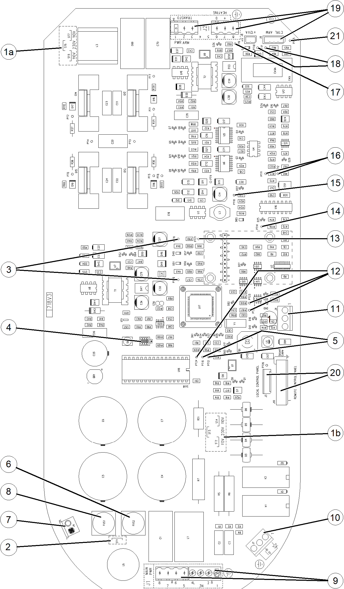
| 110V / 230V configuration | |
| 110V / 230V configuration | |
| ST1 configuration (only for 110V) | |
| 12V LED D48 and PT19 - 5V LED D51 and PT20 | |
| Dipswitches SW2 (by default, all switches are set to OFF) | |
| KV return PT13 - IHEAT return PT15 | |
| Neutral fuse (except for mobile option) | |
| “Ready” state light connector 230V - 60W max | |
| Fuse: 5A for 230V - 10A for 110V | |
| Main power supply connector | |
| Separate X-ray switch connector | |
| Synchro RVG connector | |
| I2C bus PT22 PT23 PT24 | |
| Vdac ref: PT21 | |
| KV ref: PT14 | |
| 12V non isolated: D65 and PT10 | |
| H Bridge control PT11 and PT12 | |
| VHEAT PT16 and D41 | |
| MA return PT17 Relay R control PT18 | |
| Arm cable generator | |
| J10 or J3 timer connector | |
| Ground - 0 mA PT25 |
Before installing the CJ718 powerboard, you must check its configuration.