CS 9600 Technical Specifications
X-Ray Tube Assembly Technical Specifications
Table 4 - Filtration of the Material in the X-Ray Field
|
Standard |
Compliance |
|
IEC 60601-1-3 |
Compliant |
|
Nominal value of the inherent filtration at 70 kV |
2.5 mm (0.10”) eq. Al |
|
Nominal value of the supplementary filtration at 70 kV |
1.5 mm Al or 2.0 mm Al or 0.15 mm Cu or 0.7 mm Cu |
|
Nominal value of the total filtration at 70 kV |
>2.5 mm (0.10”) eq. Al |
|
Filtration value for the enclosure of the X-ray tube (at 100 kV) |
0.2 mm (0.008") |
|
Filtration value for the enclosure of the image receiver unit (at 100 kV) |
0.2 mm (0.008") |
|
Filtration value for the sensor case |
0.3 mm (0.012") eq. Al |
The X-ray generator comprises the following:
-
A transformer and an X-ray tube and their associated electronic components immersed in oil.
-
An aluminum filter, which enhances the quality of the beam and reduces the dose received by the patient.
-
A lead collimator, which limits the size of the beam at the image receiver unit.
-
A thermal cutout, which trips at an operating temperature between 63 to 70 °C (±5 °C).
-
A copper filter.
Figure 3—Location of the Reference Axis for Panoramic and 3D Modality
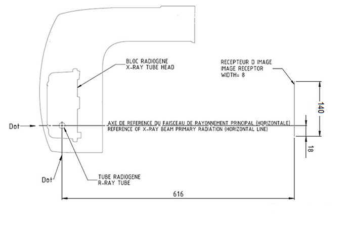
Figure 4—Location of the Reference Axis for Cephalometric Modality (with Scan Ceph Configuration)
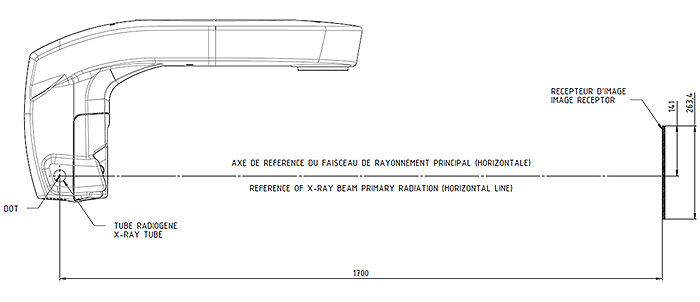
Table 5—Technical Specifications of the X-Ray Tube Assembly
|
Standard |
Compliance |
|
Manufacturer |
Trophy |
|
Degree of protection against electric shock |
Class I |
|
Degree of patient protection from the parts applied to the leakage current |
Type B |
|
Operation mode |
Continuous operation with intermittent loading |
|
Maximum accumulated heat |
33 kJ |
|
Maximum continuous heat dissipation |
60 W |
|
Tolerances on the position of the focal spot |
± 1.5 mm |
|
Continuous Anode Input Power that corresponds to the maximum specified energy input to the Anode |
60 W |
|
Radiation leakage after one hour's operation (maximum utilization rate of 60W) |
< 1 mGy |
|
Weight |
8.2 kg |
|
Dimensions |
235 x 245 x 120 mm |
 |
IMPORTANT: To increase the operating life of the X-ray tube, at the first loading or if the unit has not been used for a month, you must follow the following procedures before use. |
-
In the 3D Acquisition interface, select the following series of parameter settings:
- 70 kV – 6.3 mA
- 80 kV – 10 mA
- 85 kV – 10 mA
- 100kV – 8 mA
- 120 kV – 8 mA
-
Leave the X-ray room and close the door. For each parameter setting, from the X-ray remote control, press and hold the button to launch the X-ray.
The unit is now ready to be used for acquisition.
Figure 5—Heating and Cooling Curves of the X-Ray Tube DF-071G
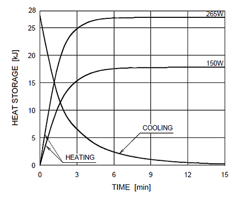
Figure 6—Heating and Cooling Curves of the X-Ray Tube OX/120-0307
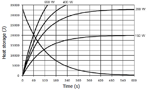
Table 6—Beam Limitations of the X-Ray Tube Assembly
|
Manufacturer |
Trophy |
|
Type |
Rigidly mounted unit with fixed window dimensions, not removable, and integrated x-ray generator |
|
Maximum symmetrical field of radiation in panoramic mode at a distance of 616 mm from the focal point |
6.4 mm x 140 mm |
|
Maximum symmetrical field of radiation in panoramic mode (sinus exam) and in 3D mode at a distance of 616 mm from the focal point |
120 mm x 140 mm |
|
Maximum symmetrical field radiation in cephalometric mode (with Scan Ceph configuration only) at a distance of 1700 mm from the focal point |
5 mm x 260 mm |
|
Location of the reference axis |
Table 7—Characteristics of the X-Ray Tube
|
Manufacturer’s name |
Toshiba or Canon |
CEI |
|
Type |
DF-071G |
OX/120-0307 |
|
Nominal high voltage |
120 kV |
120 kV |
|
Nominal anode input power (at 1.0 s) |
1360 W for Large Focus 440 W for Small Focus |
1900 W for Large Focus 500 W for Small Focus |
|
Anode heat storage capacity |
28 kJ |
33 kJ |
|
Nominal focal spot size (EN 60336) |
0.7 mm for Large Focus 0.3 mm for Small Focus |
0.7 mm for Large Focus 0.3 mm for Small Focus |
|
Anode materials |
Tungsten |
Tungsten |
|
Target angle |
12° |
12° |
|
Inherent filtration |
0.8 mm (0.032") eq. Al |
0.5 mm (0.028") eq. Al |
Figure 7—X-Ray Tube Drawing: DF-071G
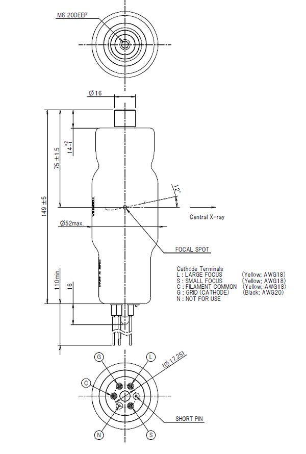
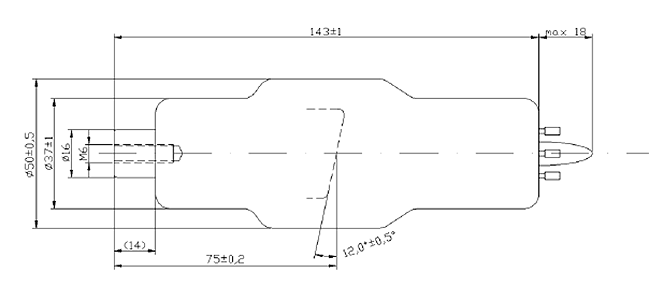
Figure 8—X-Ray Tube Drawing: OX/120-0307
CS 9600 Technical Specifications
Minimum Computer System Requirements
X-Ray Dose Emission Information
Imaging Performance Information