CS 9600 Technical Specifications
User Dose Information
Stray Radiation
Stray radiation measures are highly dependent on environmental conditions, such as the composition of walls and their locations; therefore in certain circumstances the values may be significantly different.
Measured with a PMMA phantom cylinder (Ф 16 cm x h 16 cm) at 1.0 m from the central phantom axis.
3D Mode
|
Stray radiation for one exam 16 x 10 HR @ 120 kV or 90 kV - 6.3 mAs – 20 s (add. filt. 0.7 mm Cu or 0.15 mm Cu ) |
||||||||
|
ANGLE |
Deg. |
-135 |
-90 |
-45 |
0 |
45 |
90 |
135 |
|
Stray radiation* |
µGy |
22 |
23 |
21 |
21 |
20 |
17 |
16 |
|
Stray radiation 16 x 10 HR @ 120 kV or 90 kV- maximum output power (60W – 14 x exams per hour) (add. filt. 0.7 mm Cu or 0.15 mm Cu) |
||||||||
|
ANGLE |
Deg. |
-135 |
-90 |
-45 |
0 |
45 |
90 |
135 |
|
Stray radiation* |
µGy |
314 |
329 |
300 |
300 |
286 |
243 |
229 |
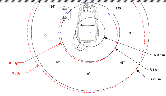
*Maximum values measured 20 cm below the horizontal cross sectional plane with chin rest. Other values in the vertical axis are lower than these values.
3D isodose curves for one exam.
Panoramic Mode
|
Stray radiation for one exam PANORAMIC STD @ 73 kV - 8 mA - 12.3 s (add. filt. 1.5 mm Al) |
||||||||
|
ANGLE |
Deg. |
-135 |
-90 |
-45 |
0 |
45 |
90 |
135 |
|
Stray radiation* |
µGy |
1 |
1.1 |
0.8 |
0.9 |
0.8 |
0.7 |
0.8 |
|
Stray radiation PANORAMIC STD @ 73 kV - maximum output power (60W – 30 x exams per hour) (add. filt. 1.5 mm Al) |
||||||||
|
ANGLE |
Deg. |
-135 |
-90 |
-45 |
0 |
45 |
90 |
135 |
|
Stray radiation* |
µGy |
30 |
33 |
24 |
27 |
24 |
21 |
24 |
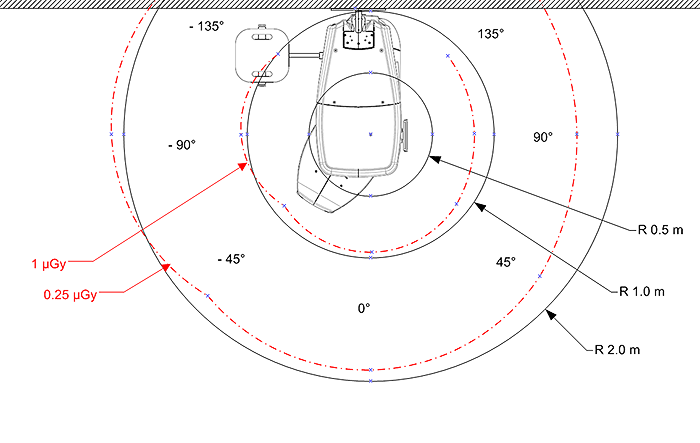
*Maximum values measured 20 cm below the horizontal cross sectional plane with chin rest. Other values in the vertical axis are lower than these values.
Panoramic isodoses curves for one exam.
CS 9600 Technical Specifications
Minimum Computer System Requirements
X-Ray Dose Emission Information
Imaging Performance Information
CS 9600 Environmental Requirements