The CS 9300 imaging unit is used for these radiological examinations:
Panoramic and segmented panoramic images
Maxillary sinus
Temporomandibular joints (TMJ)
3D images
Dental volumetric reconstruction with ENT
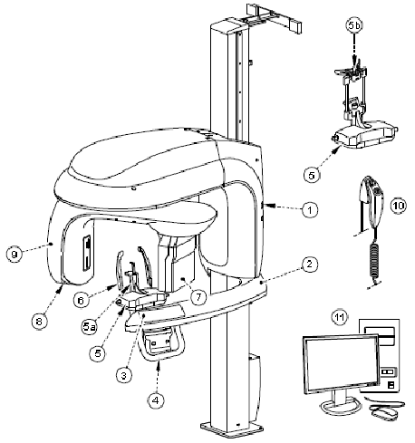
The following figure shows the components of the CS 9300:
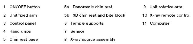
The following figure shows the location of the lasers in the CS 9300 unit:
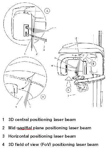
The control panel is an alphanumeric, digital soft touch console. It displays operating parameters and error messages.
The control panel components have the following functions:
1 Height Adjustment buttons—Adjusts the height of the unit to the height of the patient.
2 3D Head Adjustment buttons—Adjusts the patient’s head to the x-ray beams.
3 3D Adjustment buttons—Adjusts the unit arm movements to correctly position the patient for 3D acquisition.
4 Laser Beam button—Activates the beams to correctly position the patient.
5 Target Position button—Positions the unit arm at the selected position.
6 Reset button—Resets the unit arm to the initial position to enable the patient to enter and exit the unit.
7 Not used.
8 Display screen—Displays the current acquisition parameters and the error messages.
9 Ready indicator LED—Green indicates the unit is ready for acquisition.
10 X-ray emission LED—Yellow indicates x-rays are being emitted.
11 System status LED—Red indicates error alerts.
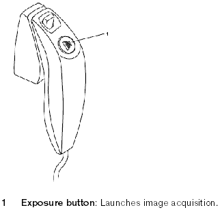
The x-ray remote control enables you to launch a radiological image acquisition using the exposure button outside the x-ray room. You must press and hold the exposure button until the end of acquisition.
Note: Premature release of the exposure button interrupts the acquisition.
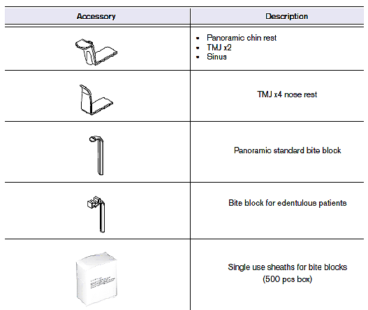
In addition to the basic components, the following panoramic accessories are delivered with the CS 9300:
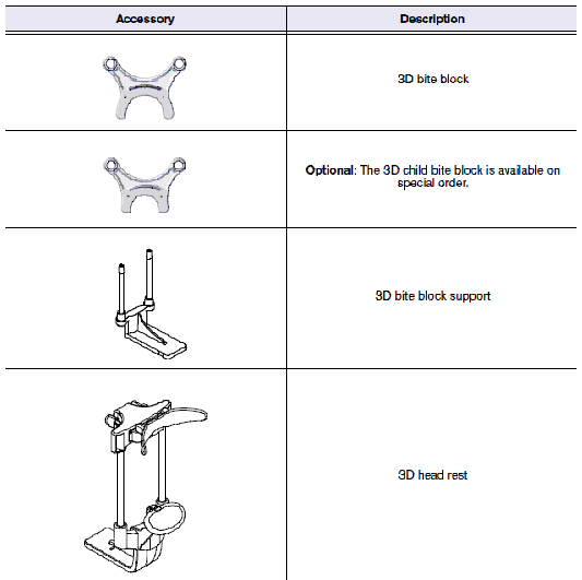
The following 3D accessories are delivered with the CS 9300:
See the CS 9300 Family User Guide (SM748) for more information.