Working With View Screens in the Workspace Tabs
View Screen Toolbars
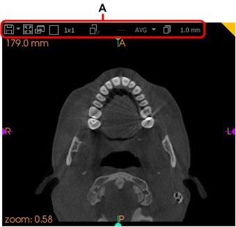
Each view screen has a toolbar at the top (A).

The following buttons are available in a view screen toolbars, depending on the view screen you are viewing.
|
DICOM Snapshot |
Click this button to create a snapshot of the selected view screen in the Gallery. Click the drop-down arrow alongside this button to toggle to the View Snapshot button. Note: These are saved as DICOM files in the screen captures folder. See “Opening the Screenshot Folder”. |
|
View Snapshot |
Click this button to create an image of the selected view screen in the Gallery. Click the drop-down arrow alongside this button to toggle to the DICOM Snapshot button. Note: These are saved as image files in the screen captures folder in the format specified in the “Export Preferences”. See “Creating a Workspace Screenshot”. |
|
Maximize |
Click this button to maximize the view screen. All other view screens will be reduced and displayed on the right side of the tab. |
|
Minimize |
Click this button to restore the maximized view screen to normal size. Note: This button is only visible in a view screen that has been maximized. |
|
Dual Screen |
Click this button to open the view screen in a separate window which you can then drag to another monitor (if you are using two or more monitors). |
|
Split View |
Click this button to change the arrangement of slices displayed in the view screen to 1x1, 3x3, 5x5, 1x3, 3x1, 1x5, or 5x1. See “Using Split Views in 2D MPR Views”. Note: This setting is not available in the 3D View Screen. |
|
Split Spacing |
Click this button to adjust the spacing between slices when the Split View option is set to 3x3, 5x5, 1x3, 3x1, 1x5, or 5x1. See “Changing the Slice Spacing in 2D MPR View Screens”. Note: This is inactive when the Split View option is set to 1x1. |
|
Set Integration |
Click this button to increase or decrease the slice thickness. Note: This is only active when the Split View option is set to 1x1. |
|
Set Integration Mode |
Click this button to set the integration mode between slices. You can choose from Averaging [AVG] and Maximum Intensity Pixel/Projection [MIP]. You can use this tool to artificially enhance contrast to increase the visibility of denser structures in the anatomy (for example cortical bone, enamel metal), which is useful for visualizing impacted or supernumerary teeth or for use in orthodontic pseudo-cephalometry. Note: This tool is only active when the Split View option is set to 1x1. If you select the MIP integration mode, then you need to set the Set Integration value to greater than 300µm. |


