Working with Images > Drawings, Measurements, and Annotations
Adding an Implant
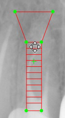
The Implant Simulator tool allows you to add a virtual implant to an image.
To add an implant to an image, follow these steps:
-
View the image in the Image Viewing Workspace or Darkroom mode.
-
In the
 Drawings & Annotations toolbar, in the Implant icon group, click
  .
.
|
|
Note: If a white triangle is displayed in the lower corner of the icon, you can access the different tools in the icon group. See Using Icon Groups. |
-
Click on the image at the point where you want to place the implant.
An implant is added to the image in the current color selection and the Implants window is displayed.
|
|
Tip: To change the implant color, see Changing Object Color and Line Thickness. |
-
In the Implants window, do any of the following:
|
To resize the implant... |
Configure the following dimensions:
|
|
To move the implant... |
Click on the implant. The pointer changes to Drag the implant to a new position.
|
|
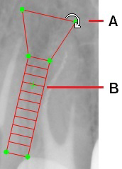
To rotate the implant... |
Move the mouse pointer over one of the implant’s rotation grab handles. The pointer changes to Click on a rotation grab handle (A) and drag around the center of the implant object. The implant object is rotated. As the object rotates, the center of rotation is indicated by a “+” (B)
|
Drawings, Measurements, and Annotations
Drawing a Multi-Segment Line (Polyline)
Adding a Text Annotation to an Image
Using the Undo and Redo Functions
Changing Object Color and Line Thickness
Using Measurements to Calculate Distances and Angles
Using the Densitometric Analysis Tool


 .
.